1889-1896
See also Pacific Railway Company
The Los Angeles Cable Railway Company is now constructing a double track wire-cable railway from the western to the eastern limits of the city, with a branch to the south-east. It will consist of new roads in addition to previously existing horse roads converted into cable lines, embracing over eight miles of double track, and will require three power-stations to operate the system. Additional lines are in contemplation by this Company to the extent of over 50 miles of road, leading to the various suburbs of the city. The road will be built on the plan of the Market Street Cable Railway, under the patents of the National and Pacific Cable Railway Companies, and therefore will be one of the best constructed cable roads in the world. The tracks of the Southern Pacific and other railways will be crossed by viaducts, one of them for a distance of 4,500 feet, with stations reached by convenient flights of stairs. In connection with the cable lines there will be an extensive system of short horse-car lines as feeders, which will also be double-tracked. The gauge of all the lines will be of uniform width of three feet six inches, so that in case of sudden increase of travel, horse-cars from the feeders can be coupled to the cable cars and run in trains.
| The Electric Railway Journal -1887- |
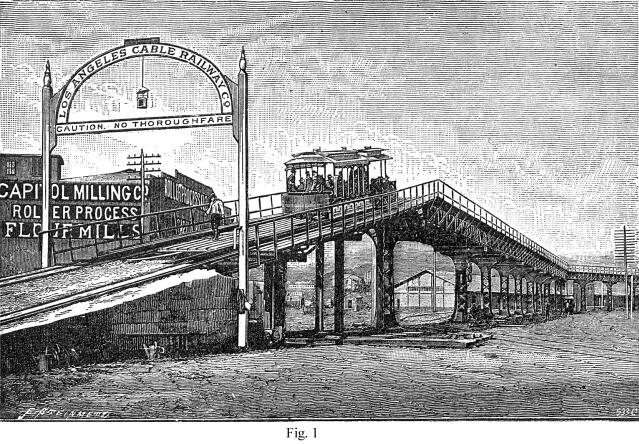
ONE of the most extensive cable-worked railroads in operation is that of Los Angeles, Cal., its length being about twenty-one miles of single track, worked by three power stations, all similar in design. In connection with this road, and serving as feeders, are twenty-four miles of horse-worked lines. The gauge is 3 ft. 6 in., and the rails, which are of steel, 40 lb. to the yard, are carried on iron sleepers. The channel in which the cable travels is made of cement concrete, and the slot rails on the top are of steel, and weigh 40 lb. per yard. The works on this line are of considerable interest, and include three viaducts, while the curves are numerous. One of the viaducts carries the line over the Santa Fe Railroad and the Los Angeles River, and is of considerable dimensions. The most important viaduct is that over San Fernando Street, and of which several views are here given.
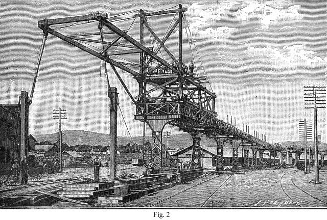
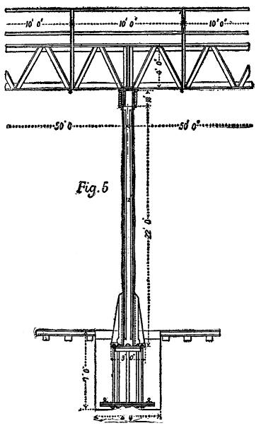
The purpose of this structure is to carry the cable lines over the Southern Pacific Railway Company's yards. The plans for it were prepared by Mr. S. G. Artingstall, of Chicago, and a remarkable feature about it is that the road is supported on single columns. This form of construction was necessitated because of a refusal on the part of both the Southern Pacific Railway Company and the city authorities to permit the planting of posts where they would have been necessary if double columns had been used; and we believe that this viaduct is the only instance in existence where two tracks are carried on single columns, although in certain parts of the elevated railway structure in New York a single track is thus supported. The length of this viaduct is 1,535 ft., of which 50 ft. at each end are occupied by concrete approaches, and the remaining 1,435 ft. represent the length of the metal work.
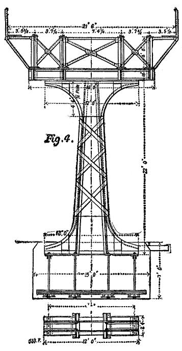
The viaduct affords no thoroughfare except for the cable cars, and in fact no other vehicles could travel over it, as the roadway is all openwork. The height from the ground to the rail level is 25 ft. 9 in., and the width between handrails is 25 ft. The main posts are 5 ft. wide at the ground line, tapering to 3 ft. at a height of 14 ft. above ground, and are 22 ft. long. There are 19
main posts, each weighing 4˝ tons, and 10 smaller posts, 12 in. square and 20ft. 6 in. long, making 29 posts in all. The ruling span is 50 ft., but there are two spans of 55 ft., three of 40 ft., one of 30 ft., and one of 20 ft. The main trusses are of the Warren type, 4 ft. deep, and weighing 100 lb. per running foot. The approaches are built of 15 I
beams, each 25 ft. long, and weighing 50 lb. per foot. The foundation for each main foot is a solid concrete block 15 ft. long, 6 ft. wide, and 5 ft. 6 in. deep. Those for the smaller posts measure 3 ft. every way. The concrete part of the approaches is 8 ft. high at the highest point and 19 ft. wide. The grade on the approaches is about 18 per cent. There are two curves on the viaduct,
each of 60 ft. radius to the center line, and at these points there are braced posts to take the strain, and the tracks are also carried on double posts at these points as well as at the approaches, as a precautionary measure.
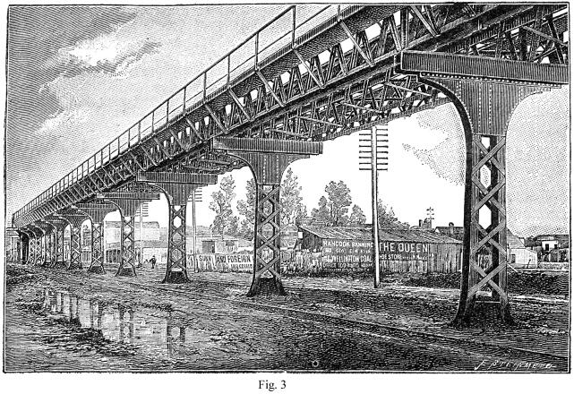
Figs. 2 and 3 are perspective views of different parts of this viaduct and give a good idea of the construction, while Figs. 4 and 5 are details of the standards and superstructure.
The entire length of the straight surface tracks of the cable line is 99,328 ft.; of the viaducts, 4,250 ft.; of bridges, 2,124 ft.; of curves, 2,010 ft.; and of the pits, 562 ft.; making a total of 108,274 ft. of track, or rather over 20˝ miles, and the construction required 1,444 tons of track and slot rails and 2,919 tons of iron sleepers.
As already stated, there are three power stations on the system, all similar in arrangement; they were completed by Messrs. Fraser & Chalmers, of Chicago, who have supplied engines to several of the cable companies in that city. The engines in the Los Angeles stations are compound; the high-pressure cylinder being 26 in. in diameter, and the low-pressure 42 in. in diameter; the
stroke is 48 in.
They are intended to develop 700 horse power at a speed of 75 revolutions per minute. The high and low pressure cylinders are set side by side, and the distance between centers is 10 ft.; the total length of built-up crankshaft is ˝in. over 14 ft. The flywheel is 14 ft. in diameter with rim of 14 in. face by 18 in. deep, and weighs 36,000 lb.
The first driving shaft of the winding machinery is 18 ft. 2˝ in. long, with two journals at the ends and one in the center between the driving rope pulleys. In the bosses of these pulleys the shaft is swelled to 16 in. in diameter. The rope wheels, which are two in number, are 6 ft. 1-and-seven-eighths in. pitch diameter; they are made in halves, and are each grooved for fourteen 2 in. cotton ropes, the power of the engines being transmitted to the driven wheels by a system of endless rope transmission instead of by gearing. The large or driven rope wheels on the main rope shaft are 25 ft. in diameter, built up of ten segments each, with a hollow boss in one piece and ten hollow arms of elliptical section. The shaft which carries these wheels is 16 ft. 1˝ inch long, the
diameter in the boss of the wheels being 19˝ in. This shaft is coupled at each end to the winding shafts, which are 11 ft. 10Ľ in. long, 17 in. in diameter in the center, and 15 in. at the bosses of the overhung rope drums. These latter are mounted on each end of the winding shaft, and each has two grooves for 2 in. cotton ropes, their diameter measured to the center of the rope being 15 ft.
They drive two other rope wheels or "idlers," which are mounted on their own shaft; these idlers are of 1 in. less diameter than the driving rope drums, and the purpose of this is always to keep the cotton ropes taut, so that the cable itself may not have to perform any of the work of rotating the idler wheels, the necessary amount of slip required, as these slightly smaller wheels gain on the
drivers, being provided for in the clutches with which the cable drums are driven. The cable drums are loose on the extended bosses of the rope wheels; and are held to these wheels by friction disks, which are tightened up by eight screws and hand-wheels in each drum. The cable drums on the winding shaft are 13 ft. in diameter with five grooves each for 1Ľ in. cable, and those on the driven shaft are of the same diameter, but with four grooves in each. The cable speed corresponding to 75 revolutions per minute of the engines is 8˝ miles an hour.
We believe that this machinery is working in a very satisfactory manner, and that it reflects much credit on its builders, Messrs. Fraser & Chalmers.—Engineering.
| Scientific American Supplement, No. 823—October 10, 1891 |
More notes:
The Broadway line opened June 8th, 1889 running on Fort Street (now Broadway) from the Plaza to Seventh and on Seventh to Grand. An extension opened September 14, 1889 on Grand from Seventh to Jefferson. A second extension opened November 2nd, 1889 on North Spring to Downey (now North Broadway), and via Downey to Pritchard (now Lincoln Park Avenue).
The powerhouses were at Seventh & Grand and Downey & Workman.
The grip was of the Eppelsheimer bottom grip type.
The company crossed the Second Street Traction Company at Second & Fort and was inferior.
The Westlake Park/Boyle Heights line opened August 3rd, 1889 on east First Street from Spring to Chicago. The line was extended on September 28th, 1889 along East First from Chicago to Evergreen. Another extension opened November 2nd, 1889 on North Spring to Downey (now North Broadway), and along Downey to Pritchard (now Lincoln Park Avenue). The final extension came on December 7th, 1889 on West Seventh from Alvarado to Grand.
The powerhouses were at Seventh & Grand and East First & Chicago.
The grip was of the Eppelsheimer bottom grip type.
The company crossed the Second Street Traction Company at Second & Fort and was inferior.
The Los Angeles Cable Railway, later known as the Pacific Railway, operated ten miles of cable and 25 miles of horse lines.
The promoters of the Los Angeles Cable Railway, Isais W. Hellman and James F. Crank, studied the first electric line in Los Angeles, the Los Angeles Electric Railway, which used the pioneering system of Professor Leo Daft. The Pico Street line was entirely unsuccessful, so Hellman and Crank chose to use the "proven" technology of cable propulsion even though their system covered very few hills.
Hellman and Crank ran short of money and sold three quarters of the company to C.B. Holmes, promoter of the Chicago City Railway. Holmes reorganized the company as the Pacific Railway. Augustine W. Wright of Chicago designed the system using patents controlled by the industry trust.
The system had several difficult features, including complicated pull curves around the Plaza, and three long viaducts used to cross rivers and mainline railroad yards.
The storm of December 24th, 1889, which destroyed the Second Street Cable Railroad, also caused damage to the Pacific Railway. The company went bankrupt on January 21st, 1891 due to storm damage and competition from Sprague electric cars of the Consolidated Electric Railway. The Consolidated Electric Railway purchased the company for a tiny fraction of its capital value on June 13th, 1893. The Los Angeles Railway Company purchased the Consolidated on October 13th, 1893.
The Los Angeles Railway, run by Frederick W. Wood, the former general manager of the Temple Street Cable Railway, strung wires above the former Los Angeles Cable tracks. On February 1st, 1896, West Seventh and Fort were shut down, and the Grand Avenue cable stopped running on the 12th. Service to Boyle Heights was converted to electricty on March 13th, 1896, and Downey Avenue was converted on the 18th.
The electric lines which replaced the Los Angeles Cable Railway were among the last in Los Angeles before the new era of light rail. They were converted, along with the Pico Street line, on March 31st, 1963.
The Los Angeles Cable Railway/Pacific Railway lost money for all concerned. Hellman continued to be a successful bank executive, he was also president of Wells Fargo Bank. Crank was bitter about the Consolidated's efforts to ruin the company. Holmes, one of the pioneers who spread cable cars beyond San Francisco, was ruined.
Return to ERHA homepage
